Showing posts with label ESP32. Show all posts

Tuesday, February 21, 2023

What is DS18B20 Temperature sensor

There are many temperature sensors that can be used with Arduino to measure temperature. Some popular choices include:

  1. DS18B20: This is a digital temperature sensor that can measure temperatures between -55°C and 125°C with an accuracy of ±0.5°C over a range of -10°C to 85°C. It communicates over a 1-Wire interface and can be easily interfaced with an Arduino.

  2. TMP36: This is an analog temperature sensor that can measure temperatures between -40°C and 125°C with an accuracy of ±1°C at 25°C. It provides a voltage output that is proportional to the temperature and can be easily interfaced with an Arduino.

  3. DHT11: This is a digital temperature and humidity sensor that can measure temperatures between 0°C and 50°C with an accuracy of ±2°C. It communicates over a 1-Wire interface and can be easily interfaced with an Arduino.

  4. LM35: This is an analog temperature sensor that can measure temperatures between -55°C and 150°C with an accuracy of ±0.5°C at 25°C. It provides a voltage output that is proportional to the temperature and can be easily interfaced with an Arduino.

The best sensor for your specific application will depend on factors such as accuracy requirements, power consumption, and cost. You should also consider whether you need a digital or analog output, and whether you need to measure humidity in addition to temperature.

 What is DS18B20 ?

The DS18B20 is a digital temperature sensor that is widely used with microcontrollers such as Arduino. It is a 1-Wire interface sensor that communicates using a single data wire and can be powered with a voltage between 3V and 5.5V. The DS18B20 can measure temperatures between -55°C and 125°C with an accuracy of ±0.5°C over a range of -10°C to 85°C.

The DS18B20 sensor has a unique 64-bit serial code that allows multiple sensors to be connected to the same data bus without conflict. It also has a programmable resolution, allowing it to output temperature readings with 9, 10, 11, or 12 bits of precision. The sensor can be used in a variety of applications, including temperature monitoring for industrial control, HVAC systems, and consumer electronics.

The DS18B20 is a popular choice for temperature sensing with Arduino because of its accuracy, simplicity of use, and low cost. There are also many libraries available for Arduino that make it easy to interface with the sensor and read temperature data.


What is the advantages over conventional temperature sensor  

The DS18B20 digital temperature sensor has several advantages over conventional analog temperature sensors:

  1. Higher accuracy: The DS18B20 has an accuracy of ±0.5°C over a range of -10°C to 85°C, which is higher than most analog temperature sensors.

  2. Digital output: The DS18B20 provides a digital output that can be easily read by a microcontroller, eliminating the need for additional analog-to-digital conversion circuits.

  3. Multiple sensors on a single data bus: With the unique 64-bit serial code of the DS18B20, multiple sensors can be connected to the same data bus, which is not possible with most analog temperature sensors.

  4. Programmable resolution: The DS18B20 can output temperature readings with 9, 10, 11, or 12 bits of precision, making it more flexible than most analog temperature sensors.

  5. Low power consumption: The DS18B20 has a low power consumption, which makes it suitable for use in battery-powered applications.

Overall, the DS18B20 provides higher accuracy, easier integration, and more flexibility than conventional analog temperature sensors, making it a popular choice for temperature sensing in a variety of applications.


How it integrate with arduino

The DS18B20 digital temperature sensor can be easily integrated with Arduino using the OneWire library and DallasTemperature library. Here are the basic steps:

  1. Connect the DS18B20 to the Arduino as follows:

  • Connect the DS18B20 data pin to a digital pin on the Arduino.

  • Connect the DS18B20 VCC pin to the Arduino 5V pin.

  • Connect the DS18B20 GND pin to the Arduino GND pin.

  1. Install the OneWire and DallasTemperature libraries in the Arduino IDE.

  2. Initialize the OneWire and DallasTemperature libraries in the Arduino sketch.

  3. Use the OneWire library to search for the DS18B20 sensor and obtain its unique 64-bit serial code.

  4. Use the DallasTemperature library to read the temperature from the DS18B20 sensor.

Here is some example code to get you started:


This code initializes the OneWire and DallasTemperature libraries, requests the temperature from the DS18B20 sensor, and prints the temperature to the Serial Monitor every second.


Monday, January 23, 2023

OTA programming in ESP32

One of the best things about ESP32 is that its firmware can be updated wirelessly. This kind of programming is called “Over-The-Air” (OTA). OTA programming lets you update/upload a new program to the ESP32 over Wi-Fi without having to connect the ESP32 to the computer via USB. The OTA functionality comes in handy when there is no physical access to the ESP module. In addition, it reduces the time required to update each ESP module during maintenance. One key advantage of OTA is that a single central location can send an update to multiple ESPs on the same network.

The only disadvantage is that you must include an OTA code with each sketch you upload in order to use OTA in the next update.

Ways To Implement OTA In ESP32

There are two ways to implement OTA functionality in the ESP32.

  • Basic OTA – updates are delivered using the Arduino IDE.
  • Web Updater OTA – updates are delivered via a web browser.

Each one has its own benefits, so you can use whichever one works best for your project.

Hear I discuss Web Updater OTA

ESP32 Over-the-air (OTA) Programming – Web Updater Arduino IDE

Quick guide that shows how to do over-the-air (OTA) programming with the ESP32 using the OTA Web Updater in Arduino IDE. The OTA Web Updater allows you to update/upload new code to your ESP32 using a browser, without the need to make a serial connection between the ESP32 and your computer.

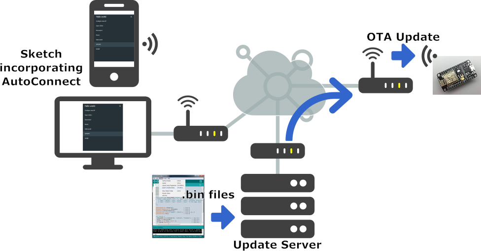
OTA Updates - AutoConnect for ESP8266/ESP32

OTA programming is useful when you need to update code to ESP32 boards that are not easily accessible. The example we’ll show here works when the ESP32 and your browser are on your local network.

The only disadvantage of the OTA Web Updater is that you have to add the code for OTA in every sketch you upload, so that you’re able to use OTA in the future.

How does OTA Web Updater Work?

  • The first sketch should be uploaded via serial port. This sketch should contain the code to create the OTA Web Updater, so that you are able to upload code later using your browser.
  • The OTA Web Updater sketch creates a web server you can access to upload a new sketch via web browser.
  • Then, you need to implement OTA routines in every sketch you upload, so that you’re able to do the next updates/uploads over-the-air.
  • If you upload a code without a OTA routine you’ll no longer be able to access the web server and upload a new sketch over-the-air.

Prerequisites

Before proceeding you should have ESP32 add-on installed in your Arduino IDE.

ESP32 OTA Web Updater

When you install the ESP32 add-on for the Arduino IDE, it will automatically install the ArduinoOTA library. Go to File > Examples >ArduinoOTA> OTAWebUpdater.

otawebupdater-arduino-ide

You should change the following lines on the code to include your own network credentials:

const char* ssid = "";
const char* password = "";

The OTAWebUpdater example for the ESP32 creates an asynchronous web server where you can upload new code to your board without the need for a serial connection.

Upload the previous code to your ESP32 board. Don’t forget to enter your network credentials and select the right board and serial port.

After uploading the code, open the Serial Monitor at a baud rate of 115200, press the ESP32 enable button, and you should get the ESP32 IP address:

Now, you can upload code to your ESP32 over-the-air using a browser on your local network.

To test the OTA Web Updater you can disconnect the ESP32 from your computer and power it using a power bank, for example (this is optional, we’re suggesting this to mimic a situation in which the ESP32 is not connected to your computer).

Update New Code using OTA Web Updater

Open a browser in your network and enter the ESP32 IP address. You should get the following:

otawebupdater-user-pass

Enter the username and the password:

  • Username: admin
  • Password: admin

You can change the username and password on the code.

Note: After you enter the username and password, you are redirected to the /serverIndex URL. You don’t need to enter the username and password to access the /serverIndex URL. So, if someone knows the URL to upload new code, the username and password don’t protect the web page from being accessible from others.

A new tab should open on the /serverIndex URL. This page allows you to upload a new code to your ESP32. You should upload .bin files (we’ll see how to do that in a moment).

ota-web-updater-esp32

Preparing the New Sketch

When uploading a new sketch over-the-air, you need to keep in mind that you need to add code for OTA in your new sketch, so that you can always overwrite any sketch with a new one in the future. So, we recommend that you modify the OTAWebUpdater sketch to include your own code.


Generate a .bin file in Arduino IDE

To generate a .bin file from your sketch, go to Sketch > Export compiled Binary

export-bin-file-arduino-ide

A new file on the folder sketch should be created. Go to Sketch > Show Sketch Folder. You should have two files in your Sketch folder: the .ino and the .bin file. You should upload the .bin file using the OTA Web Updater.

Upload a new sketch over-the-air to the ESP32

In your browser, on the ESP32 OTA Web Updater page, click the Choose File button. Select the .bin file generated previously, and then click Update.

After a few seconds, the code should be successfully uploaded.


Now your new code is ready to use.


Wednesday, October 28, 2020

Home Automation Step2

 In this step we have added Queue using cppQueue.h, it heps to save data in case of WIFI failure.

WIFI connectivity  status and Battery status also display in OLED


  #include <WiFi.h>
    #include <Wire.h>
    #include <PubSubClient.h>
    #include <Adafruit_GFX.h>
    #include <Adafruit_SSD1306.h>
    #include "DHT.h"              // DHT sensor library
    #include <NTPClient.h>
    #include "Time_a.h"  
    #include <TimeLib.h>  // unix time libray  
    #include <cppQueue.h>
    
    #define IMPLEMENTATION  FIFO
    #define queue_size 3000
    #define OVERWRITE true
    #define SCREEN_WIDTH 128 // OLED display width, in pixels
    #define SCREEN_HEIGHT 64 // OLED display height, in pixels

/////////////////////////////////////////////////////////////////////////
     #define timeSeconds 10
     // Set GPIOs for LED and PIR Motion Sensor
      const int led = 14;
      const int motionSensor = 12;
     // Timer: Auxiliary variables
      unsigned long now_delay = millis();
      unsigned long lastTrigger = 0;
      boolean startTimer = false;
      // Checks if motion was detected, sets LED HIGH and starts a timer
      void IRAM_ATTR detectsMovement() {
              Serial.println("MOTION DETECTED!!!");
              digitalWrite(led, HIGH);

              startTimer = true;
              lastTrigger = millis();
              }
////////////////////////////////////////////////////////////////
    
    
    int battery_level=38;
    
    #define DHTPIN 26     // DHT conected to  pin 26
    #define DHTTYPE DHT11 //   
    
    unsigned long offset_days = 3;    // 3 days
    //unsigned long t_unix_date1;
    
//    
//    const char* ssid     = "AndroidAP"; // change here
//    const char* password = "sema9444"; // change here
//    const char* mqtt_server = "broker.hivemq.com";

   // Change the credentials below, so your ESP8266 connects to your router
      const char* ssid = "Dialog 4G";
      const char* password = "YJNHQ102RD8";
      
   // Change the variable to your Raspberry Pi IP address, so it connects to your MQTT broker
      const char* mqtt_server = "192.168.0.105";

   // Lamp - LED - GPIO 4 = D2 on ESP-12E NodeMCU board
      const int lamp = 4;

   // Lamp - LED - GPIO 12 = D6 on ESP-12E NodeMCU board
      const int lamp1 = 5 ;

    int status = WL_IDLE_STATUS;   // the Wifi radio's status
    
    ////////////////wifi cnnected image////////////////////////////////////////////////////////////////
    static const unsigned char PROGMEM image_wifi[] = {
    // 'wifi-icon-260nw-329468402', 14x14px
    0x07, 0x80, 0x1f, 0xe0, 0x70, 0x30, 0xe3, 0x18, 0xcf, 0xcc, 0x38, 0x70, 0x30, 0x30, 0x0f, 0x80,
    0x0d, 0xc0, 0x00, 0x00, 0x03, 0x00, 0x07, 0x00, 0x03, 0x00, 0x00, 0x00};
    
    /////////////////////////battery status ///////////////////////////////////////////////////////////
    static const unsigned char PROGMEM battery_empty[] = {                                          ///
    // 'battery empty', 15x24px
    0x00, 0x00, 0x0f, 0xe0, 0x0f, 0xe0, 0x7f, 0xfc, 0x60, 0x0c, 0x60, 0x0c, 0x60, 0x0c, 0x60, 0x0c,
    0x60, 0x0c, 0x60, 0x0c, 0x60, 0x0c, 0x60, 0x0c, 0x60, 0x0c, 0x60, 0x0c, 0x60, 0x0c, 0x6f, 0xec,
    0x6f, 0xec, 0x6f, 0xec, 0x60, 0x0c, 0x60, 0x0c, 0x7f, 0xfc, 0x00, 0x00, 0x00, 0x00, 0x00, 0x00};///
                                                                                                    ///
    static const unsigned char PROGMEM battery_half[] = {                                           ///
    // 'battery half', 15x24px
    0x00, 0x00, 0x0f, 0xe0, 0x0f, 0xe0, 0x7f, 0xfc, 0x60, 0x0c, 0x60, 0x0c, 0x60, 0x0c, 0x60, 0x0c,
    0x60, 0x0c, 0x60, 0x0c, 0x6f, 0xec, 0x6f, 0xec, 0x6f, 0xec, 0x60, 0x0c, 0x60, 0x0c, 0x6f, 0xec,
    0x6f, 0xec, 0x6f, 0xec, 0x60, 0x0c, 0x7f, 0xfc, 0x7f, 0xfc, 0x00, 0x00, 0x00, 0x00, 0x00, 0x00};///
                                                                                                    ///
    static const unsigned char PROGMEM battery_full[] = {                                           ///
    // 'battery full', 15x24px
    0x00, 0x00, 0x0f, 0xe0, 0x0f, 0xe0, 0x3f, 0xfc, 0x60, 0x0c, 0x6f, 0xec, 0x6f, 0xec, 0x6f, 0xec,
    0x60, 0x0c, 0x60, 0x0c, 0x6f, 0xec, 0x6f, 0xec, 0x6f, 0xec, 0x60, 0x0c, 0x6f, 0xec, 0x6f, 0xec,
    0x6f, 0xec, 0x60, 0x0c, 0x3f, 0xfc, 0x3f, 0xf8, 0x00, 0x00, 0x00, 0x00, 0x00, 0x00, 0x00, 0x00};//
                                                                                                    ///
    ///////////////////////////////////////////////////////////////////////////////////////////////////
    WiFiClient espClient;
    PubSubClient client(espClient);
    char mqtt_msg[10];
    
    // Define NTP Client to get time
    WiFiUDP ntpUDP;
    NTPClient timeClient(ntpUDP);
    time_t et;
    
    DHT dht(DHTPIN, DHTTYPE);
    
      float dht11_hum, dht11_temp;
      uint32_t t;        //unix time
      uint32_t count=0;
      int len =0;
      Adafruit_SSD1306 display(SCREEN_WIDTH, SCREEN_HEIGHT, &Wire, -1);

     /////////////////////////////////////////////////////////////////////////////////////
       typedef struct strRec {
                  uint16_t  t;
                  float     dht11_temp;
                  float     dht11_hum;
                } Rec;

                //Rec = rec.dht11_temp;
                
                
       Queue q(sizeof(Rec), queue_size, IMPLEMENTATION,OVERWRITE); // Instantiate queue
   
    /////////////////////////////////////////////////////////////////
    void setup() {
      Serial.begin(115200);
      connect_wifi();
      update_time ();
      display.clearDisplay();         //clear OLED
/////////////////////////////////////////////////////////////////////////

      pinMode(lamp, OUTPUT);
   // pinMode(lamp1, OUTPUT)

//////////////////////////////////////////////////////////////////////////////
 // PIR Motion Sensor mode INPUT_PULLUP
    pinMode(motionSensor, INPUT_PULLUP);
 // Set motionSensor pin as interrupt, assign interrupt function and set RISING mode
    attachInterrupt(digitalPinToInterrupt(motionSensor), detectsMovement, RISING);
 // Set LED to LOW
    pinMode(led, OUTPUT);
    digitalWrite(led, LOW);
///////////////////////////////////////////////////////////////////////////////////////
    
    ///////////// to display wifi connection status https://www.arduino.cc/en/Reference/WiFiStatus   
        //if(WiFi.status()== WL_CONNECTED){
        // Draw bitmap on the screen
          display.drawBitmap(112, 0, image_wifi, 14, 14, 1);
          display.display();
       // while(true);};  
    
    ///////////////battery level display ///////////////////////////////   
    if (battery_level<30){                                           
      display.drawBitmap(110, 40, battery_empty, 15, 24, 1);display.display();};                                           
    if(battery_level>31){
       if(battery_level<50){    
       display.drawBitmap(110, 40, battery_half, 15, 24, 1);display.display();}};                                             
    if(battery_level>51){                                            
       display.drawBitmap(110, 40, battery_full, 15, 24, 1);display.display();};                                             
                                                                     
    //splay.clearDisplay();         //clear OLED                   
    ////////////////////////////////////////////////////////////////////  
    
      dht.begin();                      // Start the DHT11 sensor
      client.setServer(mqtt_server, 1883);
      client.setCallback(callback);
    }
    
    void loop() {

      
//////////////////////////////////////////////////////////////////////////////
// Current time for interruprt
   now_delay = millis();
// Turn off the LED after the number of seconds defined in the timeSeconds variable
 if(startTimer && (now_delay - lastTrigger > (timeSeconds*1000))) {
    Serial.println("Motion stopped...");
    digitalWrite(led, LOW);
    startTimer = false;
  }
//////////////////////////////////////////////////////////////////////////////

        if(len>30){
        len=0;
        Serial.println("Queue data lost !");
        }
      
    /// read data from sensors //////////////////////////////////
      dht11_hum  = dht.readHumidity();    // humidity         ///
      dht11_temp = dht.readTemperature(); // temp             ///
      t          = now();                 // time stamp       ///
                                                              ///
    /////////////////////////////////////////////////////////////
    
    ////////////// unix time convert ///////////////////
     Serial.print(t);  // https://arduino.stackexchange.com/questions/38765/convert-to-and-from-unix-timestamp
     printf("  : %4d-%02d-%02d %02d:%02d:%02d\n", year(t), month(t), day(t), hour(t), minute(t), second(t));
    
    display_oled();
    //publish_mqtt ();
    //putInQueue();
 
    //connect_wifi ();
    if(WiFi.status()==WL_CONNECTED){
    subscribeToLamps();
    putInQueuePubToMqtt();}
    
    if(WiFi.status()==WL_CONNECTION_LOST){
      Serial.println("wifi CONNECTION_LOST, Data Write to Queue");
      putInQueue();
      connect_wifi();
              if(WiFi.status()==WL_CONNECTED){
                Serial.println("Queue data due to CONNECTION_LOST");
                pubQueue ();
                Serial.println("Queue data due to CONNECTION_LOST is finished");}   
              }

    if(WiFi.status()==WL_NO_SSID_AVAIL){
      Serial.println("wifi NO_SSID_AVAIL, Data Write to Queue");
      putInQueue();
      connect_wifi();
              if(WiFi.status()==WL_CONNECTED){
                Serial.println("Queue data due to WL_NO_SSID_AVAIL");
                pubQueue ();
                Serial.println("Queue data due to WL_NO_SSID_AVAIL is finished");}   
              }

    if(WiFi.status()==WL_DISCONNECTED){
      Serial.println("wifi DISCONNECTED, Data Write to Queue");
      putInQueue();
      connect_wifi();
              if(WiFi.status()==WL_CONNECTED){
                Serial.println("Queue data due to WL_DISCONNECTED");
                pubQueue ();
                Serial.println("Queue data due to WL_DISCONNECTED is finished");
                }   
              }
    
              
     // WiFi.disconnect();
     // Serial.print("wifi Disconnected");

   
    // delay(30000);
    ////////sleep for 20 secound/////////////////////
    //  esp_sleep_enable_ext0_wakeup(GPIO_NUM_13, 0);
//      esp_sleep_enable_timer_wakeup(20000000);  
//      esp_deep_sleep_start();
      
    }
/////////////////////QUEUE/////////////////////////////////////////////////////////////////
   void subscribeToLamps(){
      client.subscribe("room/lamp");
      client.subscribe("room/lamp1");
    }
    
    
    void putInQueue (){
      
       for (int i=0; i<10; i++){
      
      dht11_hum  = dht.readHumidity();    // humidity         
      dht11_temp = dht.readTemperature(); // temp             
      t          = now();                 // time stamp   
      
      Rec rec;
      rec.t       = t;
      rec.dht11_temp = dht11_temp;
      rec.dht11_hum = dht11_hum;
      q.push(&rec);
 
      delay(10000);
      len=q.getCount();
      Serial.println(" ");
      Serial.print(len);}
 
  }

 void pubQueue(){
 
      len=q.getCount();
      for(len ;len>0; len--){
      Rec rec;
      q.pop(&rec);
      Serial.print(rec.t); Serial.print(" ");
      Serial.print(rec.dht11_temp); Serial.print(" ");
      Serial.print(rec.dht11_hum); Serial.print(" ");
      Serial.println(len);

      sprintf(mqtt_msg,"%u %2.0f %2.1f",t,dht11_hum,dht11_temp);
      //client.connect("mel5405-2018AE03");
      client.publish("mel5405/2018AE03/all",mqtt_msg);
      Serial.println(mqtt_msg);
      //delay(5000);
      delay(300);
     }
     len=0;
 }


  //////////////////////QUEUE TO MQTT ///////////////////////////////////////////////
  void putInQueuePubToMqtt(){
    for (int i=0; i<5; i++){
      
      dht11_hum  = dht.readHumidity();    // humidity         
      dht11_temp = dht.readTemperature(); // temp             
      t          = now();                 // time stamp   
      
      Rec rec;
      rec.t       = t;
      rec.dht11_temp = dht11_temp;
      rec.dht11_hum = dht11_hum;
      q.push(&rec);
      delay(10000);}
    
    len=q.getCount();
    if(len%5==0){
      for(len ;len>0; len--){
      Rec rec;
      q.pop(&rec);
      Serial.print(rec.t);
      Serial.print(" ");
      Serial.print(rec.dht11_temp);
      Serial.print(" ");
      Serial.print(rec.dht11_hum);
      Serial.print(" ");
      Serial.println(len);

      sprintf(mqtt_msg,"%u %2.2f %2.2f",rec.t,rec.dht11_temp,rec.dht11_hum);
      client.connect("mel5405-2018AE03");
      client.publish("mel5405/2018AE03/all",mqtt_msg);
      Serial.println(mqtt_msg);
      delay(500);
      
      sprintf(mqtt_msg," %2.2f",rec.dht11_temp);
      client.connect("mel5405-2018AE03");
      client.publish("mel5405/2018AE03/temp",mqtt_msg);
      Serial.println(mqtt_msg);
      delay(500);


//      sprintf(mqtt_msg," %2.2f",rec.dht11_hum);
//      client.connect("mel5405-2018AE03");
//      client.publish("mel5405/2018AE03/hum",mqtt_msg);
//      Serial.println(mqtt_msg);
//      delay(500);
  //  delay(5000);
      
  //  delay(300);
     }
     len=0;
    }
  }


  ////////////////////////////////////////////////////////////////////////////////  
//    void publish_mqtt() {
//      ////////////////// publish data using MQTT////////////////////////////////   
//      sprintf(mqtt_msg,"%2.4f",dht11_hum);
//      client.connect("mel5405-2018AE03"); // change here
//      client.publish("mel5405/2018AE03/humidity", mqtt_msg);  // change here
//      Serial.println(mqtt_msg);
//      delay(5000);
//      sprintf(mqtt_msg,"%2.4f",dht11_temp);
//      client.connect("mel5405-2018AE03"); // change here
//      client.publish("mel5405/2018AE03/temp", mqtt_msg);   // change here
//      Serial.println(mqtt_msg);
//      delay(5000);
//      sprintf(mqtt_msg,"%u",t);
//      client.connect("mel5405-2018AE03"); // change here
//      client.publish("mel5405/2018AE03/time", mqtt_msg);  // change here
//      Serial.println(mqtt_msg);
//      delay(5000);
//      sprintf(mqtt_msg,"%2.0f-%2.1f",dht11_hum,dht11_temp);
//      client.connect("mel5405-2018AE03");
//      client.publish("mel5405/2018AE03/all",mqtt_msg);
//      Serial.println(mqtt_msg);
//      delay(5000);
//    }
    void display_oled(){
      /////////////Display data on OLED ///////////////////////////
    
      display.setTextSize(1);         //set OLED text size
      display.setTextColor(WHITE);    // set text colour
      display.print(WiFi.localIP());  //Display IP of ESP
      delay(2000);
      //display.clearDisplay();       //clear OLED
     
      display.setTextSize(2);         // Draw 2X-scale text
      display.setTextColor(WHITE);
      display.setCursor(2, 15);
      display.print(dht11_temp);
      display.print(" C");
      display.setCursor(2, 30);
      display.print(dht11_hum);
      display.print(" %");
      display.setTextSize(1);         // Draw 1X-scale text
      display.setCursor(1, 55);
      display.print(t);
      display.setCursor(64, 55);
      display.print(count);
      display.display();
    }
    
    void update_time(){
    
      ///////////////// time update///////////////////////////////////////////////////
       timeClient.begin();
       timeClient.setTimeOffset(0); // GMT +5:30 = 19800
       while(!timeClient.update()) {
       timeClient.forceUpdate();
       delay(100);
       Serial.print("*");
       count ++;
       if (count>3)break;}


       if (count<3){
            Serial.println("");
            Serial.print("NTP time set: ");
            setTime(timeClient.getEpochTime());  // update ESP32 time
           }
       else {
            Serial.println("");
            Serial.println("Time not set");
            }
        if(!display.begin(SSD1306_SWITCHCAPVCC, 0x3C)) { // Address 0x3D for 128x64
        Serial.println(F("SSD1306 allocation failed"));
        for(;;);
      }
     
      delay(100);
      }
    
    void connect_wifi(){
            int count=0;
            Serial.print("Connecting to ");
            Serial.println(ssid);
            WiFi.begin(ssid, password);

            while (WiFi.status() != WL_CONNECTED) {
            delay(500);
            Serial.print(".");
            count ++;
            if (count>40)break;}

            if (count<40){
            Serial.println("");
            Serial.print("Connected to WiFi network with IP Address: ");
            Serial.println(WiFi.localIP());}
                       
            else {(Serial.print("No WiFi"));
               }
        }
void callback(String topic, byte* message, unsigned int length) {
  Serial.print("Message arrived on topic: ");
  Serial.print(topic);
  Serial.print(". Message: ");
  String messageTemp;
 
  for (int i = 0; i < length; i++) {
    Serial.print((char)message[i]);
    messageTemp += (char)message[i];
  }
  Serial.println();

  // Feel free to add more if statements to control more GPIOs with MQTT
  if(topic=="room/lamp1"){
      Serial.print("Changing Room lamp1 to ");
      if(messageTemp == "on"){
        digitalWrite(lamp1, HIGH);
        Serial.print("On");
      }
      else if(messageTemp == "off"){
        digitalWrite(lamp1, LOW);
        Serial.print("Off");
      }
  }
  Serial.println();
  // If a message is received on the topic room/lamp, you check if the message is either on or off. Turns the lamp GPIO according to the message
  if(topic=="room/lamp"){
      Serial.print("Changing Room lamp to ");
      if(messageTemp == "on"){
        digitalWrite(lamp, HIGH);
        Serial.print("On");
      }
      else if(messageTemp == "off"){
        digitalWrite(lamp, LOW);
        Serial.print("Off");
      }
  }
  Serial.println();
}

Search This Blog