Parts Required
ESP32-CAM with OV2640 ( ESP32-CAM - Ai-Thinker )
FTDI programmer
Old RC car to make a chassis of car
L298N Motor Driver Unit
Introducing the ESP32-CAM
ESP32-CAM Pinout
Video Streaming Server for testing your first code
first, let's test our video streaming server, then go to project back,
1. Install the ESP32 add-on
Open the Arduino IDE (Integrated Development Environment).
Go to "File" and select "Preferences."
In the "Additional Boards Manager URLs" field, add the following URL: https://dl.espressif.com/dl/package_esp32_index.json
Click "OK" to save the changes.
Go to "Tools" and select "Board: " and then "Boards Manager."
In the "Boards Manager" window, search for "esp32" and select "esp32 by Espressif Systems" from the results.
Click the "Install" button to install the ESP32 add-on.
Once the installation is complete, close the "Boards Manager" window.
Go to "Tools" and select "Board: " and then "ESP32 Dev Module" from the list of boards.
You're now ready to use the ESP32 with Arduino!
2. Camera Web Server from Example Code
3. ESP32-CAM Upload Code using FTDI programmer
Upload Code with Arduino IDE
To upload code to the ESP32-CAM (AI-Thinker) using Arduino IDE, follow the next exact steps.
Connect the ESP32-CAM board to your computer using an FTDI programmer. Follow the next schematic diagram:
| ESP32-CAM | FTDI Programmer | |||||||
| GND | GND | |||||||
| 5V | VCC (5V) | |||||||
| U0R | TX | |||||||
| U0T | RX | |||||||
| GPIO 0 | GND |
To upload code to the ESP32-CAM using Arduino IDE,
1) Go to Tools > Board and select AI-Thinker ESP32-CAM. You must have the ESP32 add-on installed. Otherwise, this board won’t show up on the Boards menu.
2) Go to Tools > Port and select the COM port the ESP32-CAM is connected to.
3) For demonstration purposes, you can upload a blank sketch to your board:
void setup() {
  // put your setup code here, to run once:
}

void loop() {
  // put your main code here, to run repeatedly:
}
4) Then, click the Upload button in your Arduino IDE.

5) When you start to see some dots on the debugging window, press the ESP32-CAM on-board RST button.


7) Now you can upload final code to control RC car.
https://github.com/almorawaka/ESP32-CAM-RC-car-with-camera.gitGo to my git hub and download code and update SSID and PW in the code. Select proper Module and Upload the code
8) Solder the circuit connections as follows
Start by connecting the ESP32-CAM to the motor driver as shown in the schematic diagram. You can either use a mini breadboard or a stripboard to place your ESP32-CAM and build the circuit.
The following table shows the connections between the ESP32-CAM and the L298N Motor Driver.
4. Getting the IP address of your server
When you upload this code to your ESP32-CAM module and open the Serial Monitor in the Arduino IDE, you should see the module connecting to your Wi-Fi network and obtaining an IP address. The IP address will be printed in the Serial Monitor.
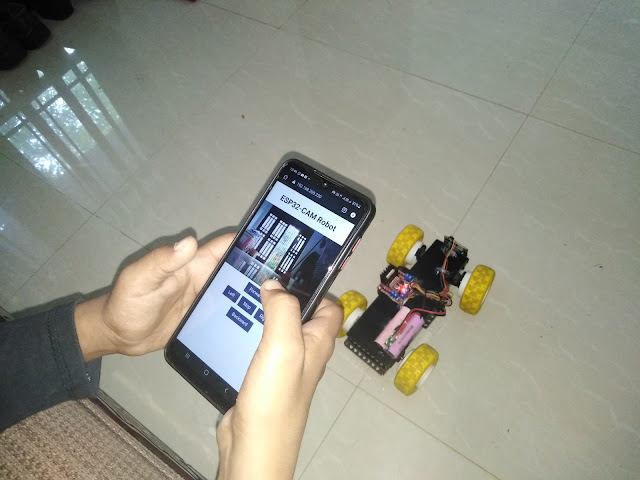
Open a browser on the ESP32-CAM IP address, and you should be able to control your robot. The web server works well on a laptop computer or smartphone.


No comments:
Post a Comment