What is MPU 6050 ?
The MPU-6050 is an integrated 6-axis motion tracking device that combines a 3-axis gyroscope and a 3-axis accelerometer on a single microchip. It is commonly referred to as the GY-521 module and is used in a variety of applications, such as drone stabilization systems, wearable devices, and gaming controllers.
The device communicates with microcontrollers and single-board computers, such as the Arduino, via the I2C interface. The MPU-6050 provides raw accelerometer and gyroscope data that can be processed using a Kalman filter or complementary filter to obtain a more accurate estimate of the device's orientation in space.
The MPU-6050 is a low-cost and widely available device that is well-suited for a variety of motion tracking applications.
MPU6050 (GY521)

Following information can be read out from the MPU6050.
- Acceleration along three mutually perpendicular axes with a programmable full scale range of ±2g, ±4g, ±8g and ±16g. This measurement includes the acceleration due to gravity.
- Angular velocity around three mutually perpendicular axes, with a user-programmable full-
scale range of ±250, ±500, ±1000, and ±2000°/sec - Temperature
To integrate the MPU-6050 with a Raspberry Pi, you will need to follow these steps:
Connect the MPU-6050 to the Raspberry Pi: Connect the VCC pin of the MPU-6050 to the 3.3V pin of the Raspberry Pi, GND to GND, SDA to SDA (GPIO 2), and SCL to SCL (GPIO 3).
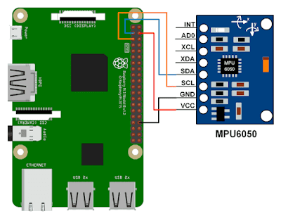
Enable I2C on the Raspberry Pi: You will need to enable the I2C interface on your Raspberry Pi in order to communicate with the MPU-6050. This can be done through the Raspberry Pi Configuration tool in the Preferences menu, or by adding the following line to the /boot/config.txt file:

dtparam=i2c_arm=on
- Install the i2c-tools package: The i2c-tools package provides the necessary tools to communicate with I2C devices on the Raspberry Pi. You can install it by running the following command:
sudo apt-get install i2c-tools
- Test the connection: After enabling I2C and installing the i2c-tools package, you can test the connection between the Raspberry Pi and the MPU-6050 by running the following command:
sudo i2cdetect -y 1
If the MPU-6050 is connected correctly, you should see its address (0x68) in the list of I2C devices.
- Read data from the MPU-6050: To read data from the MPU-6050, you will need to write code in a programming language such as Python that reads the raw data from the sensor using the I2C interface. A number of libraries are available to simplify this process, such as the RTIMULib library, which provides a simple and easy-to-use interface to the MPU-6050.
Once you have the raw data from the MPU-6050, you can process it to obtain more useful information, such as the device's orientation in space.
// ////////////////Sample Code for reading mpu6050 using Rpi/////////////////////
// build with: gcc -o mpu6050 mpu6050.c
#include <stdio.h>
#include <stdlib.h>
#include <fcntl.h>
#include <unistd.h>
#include <string.h>
#include <sys/ioctl.h>
#include <sys/types.h>
#include <sys/stat.h>
#include <linux/i2c-dev.h>
#include <math.h>
#define MPU_GYRO_CONFIG 0x1b
#define MPU_ACCEL_CONFIG 0x1c
#define MPU_ACCEL_XOUT1 0x3b
#define MPU_ACCEL_XOUT2 0x3c
#define MPU_ACCEL_YOUT1 0x3d
#define MPU_ACCEL_YOUT2 0x3e
#define MPU_ACCEL_ZOUT1 0x3f
#define MPU_ACCEL_ZOUT2 0x40
#define MPU_GYRO_XOUT1 0x43
#define MPU_GYRO_XOUT2 0x44
#define MPU_GYRO_YOUT1 0x45
#define MPU_GYRO_YOUT2 0x46
#define MPU_GYRO_ZOUT1 0x47
#define MPU_GYRO_ZOUT2 0x48
#define MPU_TEMP1 0x41
#define MPU_TEMP2 0x42
#define MPU_POWER1 0x6b
#define MPU_POWER2 0x6c
void selectDevice(int fd, int addr, char * name)
{
if (ioctl(fd, I2C_SLAVE, addr) < 0) {
fprintf(stderr, "%s not present\n", name);
}
}
void selectRegister(int fd, int reg)
{
char buf[1];
buf[0]=reg;
if (write(fd, buf, 1) != 1) {
fprintf(stderr, "Can't write\n");
}
}
void writeToDevice(int fd, int reg, int val)
{
char buf[2];
buf[0]=reg; buf[1]=val;
if (write(fd, buf, 2) != 2) {
fprintf(stderr, "Can't write\n");
}
}
int main(int argc, char **argv)
{
int fd;
char *fileName = "/dev/i2c-2";
int address = 0x68;
unsigned char buf[16];
float T;
float xa,ya,za,acc_scale=16384.0;
float xg,yg,zg,gyro_scale=131.0;
int8_t p;
if ((fd = open(fileName, O_RDWR)) < 0) {
printf("Failed to open i2c port\n");
exit(1);
}
selectDevice(fd,address,"MPU6050");
// MPU6050 is in sleep mode upon power on.
// To wake up, bit 6 of register MPU_POWER1 must be set to 0
selectRegister(fd,MPU_POWER1);
read(fd,buf,1); // read the current value of MPU_POWER1
p = buf[0];
selectRegister(fd,MPU_POWER1);
writeToDevice(fd,MPU_POWER1,~(1 << 6) & p); // set bit 6 to zero and write to MPU_POWER1
// set gyro scale to +/- 250
selectRegister(fd,MPU_GYRO_CONFIG);
read(fd,buf,1); // read the current value
p = buf[0];
selectRegister(fd,MPU_GYRO_CONFIG);
writeToDevice(fd,MPU_GYRO_CONFIG,~(3 << 3) & p); // set bits 3 and 4 to 11
// set accel scale to +/- 2g
selectRegister(fd,MPU_ACCEL_CONFIG);
read(fd,buf,1); // read the current value
p = buf[0];
selectRegister(fd,MPU_ACCEL_CONFIG);
writeToDevice(fd,MPU_ACCEL_CONFIG,~(3 << 3) & p); // set bits 3 and 4 to 11
while (1) {
selectRegister(fd,MPU_TEMP1); // temperature
read(fd,buf,2); // read 2 registers (low byte and high byte)
int16_t temp = buf[0]<<8 | buf[1]; // combine the two bytes
selectRegister(fd,MPU_ACCEL_XOUT1);
read(fd,buf,2);
int16_t xaccel = buf[0]<<8 | buf[1];
xa = xaccel/acc_scale; // convert to g
selectRegister(fd,MPU_ACCEL_YOUT1);
read(fd,buf,2);
int16_t yaccel = buf[0]<<8 | buf[1];
ya = yaccel/acc_scale; // convert to g
selectRegister(fd,MPU_ACCEL_ZOUT1);
read(fd,buf,2);
int16_t zaccel = buf[0]<<8 | buf[1];
za = zaccel/acc_scale; // convert to g
selectRegister(fd,MPU_GYRO_XOUT1);
read(fd,buf,2);
int16_t xgyro = buf[0]<<8 | buf[1];
xg = xgyro/gyro_scale; // convert
selectRegister(fd,MPU_GYRO_YOUT1);
read(fd,buf,2);
int16_t ygyro = buf[0]<<8 | buf[1];
yg = ygyro/gyro_scale; // convert
selectRegister(fd,MPU_GYRO_ZOUT1);
read(fd,buf,2);
int16_t zgyro = buf[0]<<8 | buf[1];
zg = zgyro/gyro_scale; // convert
T = temp / 340.0f + 36.53;
printf("temp: %f\n",T );
printf("accel x,y,z: %f, %f, %f\n", xa, ya,za);
printf("gyro x,y,z: %f, %f, %f\n\n", xg,yg,zg);
sleep(1); // delay
}
return 0;
}

