Wednesday, December 11, 2019

ADXL345 Collecting data and plotting with GNU Octave


int main () {
FILE * fp;
....


while (1) {
....

fp = fopen ("mpu6050.dat", "a");

fprintf(fp," %f, %f, %f %f, %f, %f, %f \n", xa, ya,za,xg,yg,zg,T);
fclose(
fp);
sleep(1);
}


Complete code 
 
// Build with:     gcc -o adxl345 adxl345.c

    #include <stdio.h>
    #include <stdlib.h>
    #include <fcntl.h>
    #include <unistd.h>
    #include <string.h>
    #include <sys/ioctl.h>
    #include <sys/types.h>
    #include <sys/stat.h>
    #include <linux/i2c-dev.h>

    #define ADXL345_I2C_ADDR 0x53

    void selectDevice(int fd, int addr, char * name)
    {
       if (ioctl(fd, I2C_SLAVE, addr) < 0)
       {
          fprintf(stderr, "%s not present\n", name);
          //exit(1);
       }
    }

    void selectRegister(int fd, int reg)
    {
       char buf[1];
       buf[0]=reg;
       if (write(fd, buf, 1) != 1)  {
          fprintf(stderr, "Can't write to i2c slave\n");
       }
    }

   
    void writeToDevice(int fd, int reg, int val)
    {
       char buf[2];
       buf[0]=reg; buf[1]=val;
       if (write(fd, buf, 2) != 2)
       {
          fprintf(stderr, "Can't write to ADXL345\n");
       }
    }

    int main(int argc, char **argv)
    {

     FILE * fp;
       unsigned int range;
       int count, b;
       short x, y, z;
       float xa, ya, za;
       int fd;
       unsigned char buf[16];
      
       if ((fd = open("/dev/i2c-1", O_RDWR)) < 0)
       {
          // Open port for reading and writing
          fprintf(stderr, "Failed to open i2c bus\n");
          exit(1);
       }
      
       selectDevice(fd, ADXL345_I2C_ADDR, "ADXL345");

       writeToDevice(fd, 0x2d, 0);
       writeToDevice(fd, 0x2d, 16);
       writeToDevice(fd, 0x2d, 8);
       writeToDevice(fd, 0x31, 0);
       writeToDevice(fd, 0x31, 11);

       while (1)
       {  
          selectDevice(fd, ADXL345_I2C_ADDR, "ADXL345");
          selectRegister(fd,0x32 );
     
          if (read(fd, buf, 6) != 6)   {   //  X, Y, Z accelerations
             fprintf(stderr, "Unable to read from ADXL345\n");
          }
          else
          {
             x = buf[1]<<8| buf[0];
             y = buf[3]<<8| buf[2];
             z = buf[5]<<8| buf[4];
             printf("x: %d y: %d z: %d\n", x, y, z);

     fp = fopen ("adxl345.dat", "a");

            fprintf(fp,"  %d  %d  %d\n", x, y, z);
       fclose(fp);


          }
          sleep(1);
       }
      
       return 0;
    }

################################################


can run the code in background with the command

./mpu6050 &

Because you are running the data collection code inside a NFS mounted directory, the data file generated will be directly visible from the PC. In the PC, you can see the data with the command

cat mpu6050.dat


Bus this is not a very convenient way to understand data. A better way is to plot graphs.

Plotting data

Many data plotting packages are available for visualizing data. One available in your computers is Octave.

Octave is a package very similar to Matlab. Many Matlab m-files can be executed in Octave without any change.

For plotting your data in Octave, start Octave and change directory to your NFS shared directory. Then the following commands can be used to plot the three acceleration components on the same graph.

s=load("adxl345.dat");
plot(s(:,1));
hold on
plot(s(:,2));
plot(s(:,3));


ADXL345: If you are using one of these modules, plot the three components of acceleration in one graph.

HMC5883 (GY271) and HMC5983 (GY282)

HMC5883 (GY271) and HMC5983 (GY282)
Both HMC5883 and HMC5983 are 3-axis magnetometers which measure the strength of the magnetic field along three mutually perpendicular axes with ±0.88 Ga, ±1.3 Ga, ±1.9 Ga, ±2.5 Ga, ±4.0 Ga, ±4.7 Ga, ±5.6 Ga and ±8.1 Ga resolutions. Although there are some slight differences between them, the same code can be used to read them.


// build with:    gcc -o hmc5983 hmc5983.c -lm

    #include <stdio.h>
    #include <stdlib.h>
    #include <fcntl.h>
    #include <unistd.h>
    #include <string.h>
    #include <sys/ioctl.h>
    #include <sys/types.h>
    #include <sys/stat.h>
    #include <linux/i2c-dev.h>
    #include <math.h>

    #define HMC5983_I2C_ADDR 0x1E

    void selectDevice(int fd, int addr, char * name)
    {
       if (ioctl(fd, I2C_SLAVE, addr) < 0) {
          fprintf(stderr, "%s not present\n", name);
       }
    }

    void selectRegister(int fd, int reg)
    {
       char buf[1];
       buf[0]=reg;
       if (write(fd, buf, 1) != 1)  {
          fprintf(stderr, "Can't write to HMC5983\n");
       }
    }
   
     void SelectRegister(int fd, char val)
    {
       char buf[1];
       buf[0]=val;
       if (write(fd, buf, 1) != 1)  {
          fprintf(stderr, "Can't write to HMC5983\n");
       }
    }
   
   
    void writeToDevice(int fd, int reg, int val)
    {
       char buf[2];
       buf[0]=reg; buf[1]=val;
       if (write(fd, buf, 2) != 2)   {
          fprintf(stderr, "Can't write to HMC5983\n");
       }
    }
   
   
    int main(int argc, char **argv)
    {
       unsigned int range;
       int count, b;
       short x, y, z,t;
       float xa, ya, za,ta,B;
       int fd;
       unsigned char buf[16];
      
       FILE *fptr;
      
      
       if ((fd = open("/dev/i2c-2", O_RDWR)) < 0)
       {
          // Open port for reading and writing
          fprintf(stderr, "Failed to open i2c bus\n");
          exit(1);
       }
      
       selectDevice(fd, HMC5983_I2C_ADDR, "HMC5983");
       writeToDevice(fd, 0x00, 0xf0); // CRA  - temp enabled, 8-average, 15 Hz default, normal measurement
       writeToDevice(fd, 0x01, 0x00); // CRB  - Gain=0
           
       while (1)
       {  
         writeToDevice(fd, 0x02, 0x01); // Mode - single-measurement mode

         selectRegister(fd,0x09);  // status register
         read(fd, buf, 1);
     printf("%d\n",buf[0]);

         selectRegister(fd,0x03);  // first data register
   
     if (read(fd, buf, 6) != 6) {  // read 6 data registers
             fprintf(stderr, "Unable to read from HMC5983\n");
          }
          else  {
             x = buf[0]<<8| buf[1];
             z = buf[2]<<8| buf[3];
             y = buf[4]<<8| buf[5];

//             printf("%d %d %d \n", x, y, z);
         xa = x*100.0/1370.0; //in milli tesla
         ya = y*100.0/1370.0; //in milli tesla
         za = z*100.0/1370.0; //in milli tesla
         B  = sqrt(xa*xa+ya*ya+za*za);
             printf("field : %f %f %f  %f nT\n", xa, ya, za,B);

       
      }

         selectRegister(fd,0x31);  // first data register
         
          if (read(fd, buf, 2) != 2) {  // read 6 data registers
             fprintf(stderr, "Unable to read from HMC5983\n");
          }
          else  {
             t  = buf[0]<<8| buf[1];
         ta = t/128.0+25.0;
             printf("temperature: %f C\n",ta);
          }

//           fptr = fopen("field.txt", "a");
//           printf("%f %f %f  %f  \n", xa, ya, za,ta);
//           fprintf(fptr,"%f %f %f  %f  \n", xa, ya, za,ta);
//           fclose(fptr);
          sleep(1);
       }
      
       return 0;
    }

How to use MPU6050 (GY521) with Raspberry PI

 What is MPU 6050 ?

The MPU-6050 is an integrated 6-axis motion tracking device that combines a 3-axis gyroscope and a 3-axis accelerometer on a single microchip. It is commonly referred to as the GY-521 module and is used in a variety of applications, such as drone stabilization systems, wearable devices, and gaming controllers.

The device communicates with microcontrollers and single-board computers, such as the Arduino, via the I2C interface. The MPU-6050 provides raw accelerometer and gyroscope data that can be processed using a Kalman filter or complementary filter to obtain a more accurate estimate of the device's orientation in space.

The MPU-6050 is a low-cost and widely available device that is well-suited for a variety of motion tracking applications.


MPU6050 (GY521)


The MPU6050 also categorized as Micro Electro-Mechanical Systems (MEMS) which consists of a 3-axis Accelerometer and 3-axis Gyroscope inside it.
Following information can be read out from the MPU6050.
  • Acceleration along three mutually perpendicular axes with a programmable full scale range of ±2g, ±4g, ±8g and ±16g. This measurement includes the acceleration due to gravity.
  • Angular velocity around three mutually perpendicular axes, with a user-programmable full-
    scale range of ±250, ±500, ±1000, and ±2000°/sec
  • Temperature

To integrate the MPU-6050 with a Raspberry Pi, you will need to follow these steps:

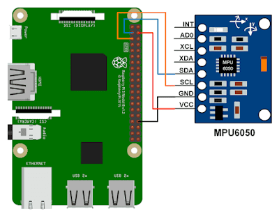
  1. Connect the MPU-6050 to the Raspberry Pi: Connect the VCC pin of the MPU-6050 to the 3.3V pin of the Raspberry Pi, GND to GND, SDA to SDA (GPIO 2), and SCL to SCL (GPIO 3).


  2. Enable I2C on the Raspberry Pi: You will need to enable the I2C interface on your Raspberry Pi in order to communicate with the MPU-6050. This can be done through the Raspberry Pi Configuration tool in the Preferences menu, or by adding the following line to the /boot/config.txt file:

dtparam=i2c_arm=on
  1. Install the i2c-tools package: The i2c-tools package provides the necessary tools to communicate with I2C devices on the Raspberry Pi. You can install it by running the following command:
sudo apt-get install i2c-tools
  1. Test the connection: After enabling I2C and installing the i2c-tools package, you can test the connection between the Raspberry Pi and the MPU-6050 by running the following command:
sudo i2cdetect -y 1

If the MPU-6050 is connected correctly, you should see its address (0x68) in the list of I2C devices.

  1. Read data from the MPU-6050: To read data from the MPU-6050, you will need to write code in a programming language such as Python that reads the raw data from the sensor using the I2C interface. A number of libraries are available to simplify this process, such as the RTIMULib library, which provides a simple and easy-to-use interface to the MPU-6050.

Once you have the raw data from the MPU-6050, you can process it to obtain more useful information, such as the device's orientation in space.


// ////////////////Sample Code for reading mpu6050 using Rpi/////////////////////
// build with:  gcc -o mpu6050 mpu6050.c

#include <stdio.h>
#include <stdlib.h>
#include <fcntl.h>
#include <unistd.h>
#include <string.h>
#include <sys/ioctl.h>
#include <sys/types.h>
#include <sys/stat.h>
#include <linux/i2c-dev.h>
#include <math.h>

#define MPU_GYRO_CONFIG 0x1b
#define MPU_ACCEL_CONFIG 0x1c

#define MPU_ACCEL_XOUT1 0x3b
#define MPU_ACCEL_XOUT2 0x3c
#define MPU_ACCEL_YOUT1 0x3d
#define MPU_ACCEL_YOUT2 0x3e
#define MPU_ACCEL_ZOUT1 0x3f
#define MPU_ACCEL_ZOUT2 0x40

#define MPU_GYRO_XOUT1 0x43
#define MPU_GYRO_XOUT2 0x44
#define MPU_GYRO_YOUT1 0x45
#define MPU_GYRO_YOUT2 0x46
#define MPU_GYRO_ZOUT1 0x47
#define MPU_GYRO_ZOUT2 0x48

#define MPU_TEMP1 0x41
#define MPU_TEMP2 0x42

#define MPU_POWER1 0x6b
#define MPU_POWER2 0x6c

    void selectDevice(int fd, int addr, char * name)
    {
       if (ioctl(fd, I2C_SLAVE, addr) < 0) {
          fprintf(stderr, "%s not present\n", name);
       }
    }

    void selectRegister(int fd, int reg)
    {
       char buf[1];
       buf[0]=reg;
       if (write(fd, buf, 1) != 1)  {
          fprintf(stderr, "Can't write\n");
       }
    }
   
  
    void writeToDevice(int fd, int reg, int val)
    {
       char buf[2];
       buf[0]=reg; buf[1]=val;
       if (write(fd, buf, 2) != 2)   {
          fprintf(stderr, "Can't write\n");
       }
    }
   

int main(int argc, char **argv)
{
    int fd;
    char *fileName = "/dev/i2c-2";
    int  address = 0x68;
    unsigned char buf[16];
    float T;
    float xa,ya,za,acc_scale=16384.0;
    float xg,yg,zg,gyro_scale=131.0;
    int8_t p;   

    if ((fd = open(fileName, O_RDWR)) < 0) {
        printf("Failed to open i2c port\n");
        exit(1);
    }
   
    selectDevice(fd,address,"MPU6050");

// MPU6050 is in sleep mode upon power on.
// To wake up, bit 6 of register MPU_POWER1 must be set to 0
    selectRegister(fd,MPU_POWER1);
    read(fd,buf,1);                                  // read the current value of MPU_POWER1
    p = buf[0];
    selectRegister(fd,MPU_POWER1);
    writeToDevice(fd,MPU_POWER1,~(1 << 6) & p); // set bit 6 to zero and write to MPU_POWER1

// set gyro scale to +/- 250   
    selectRegister(fd,MPU_GYRO_CONFIG);
    read(fd,buf,1);                                  // read the current value
    p = buf[0];
    selectRegister(fd,MPU_GYRO_CONFIG);
    writeToDevice(fd,MPU_GYRO_CONFIG,~(3 << 3) & p); // set bits 3 and 4 to 11    

// set accel scale to +/- 2g    
    selectRegister(fd,MPU_ACCEL_CONFIG);
    read(fd,buf,1);                                  // read the current value
    p = buf[0];
    selectRegister(fd,MPU_ACCEL_CONFIG);
    writeToDevice(fd,MPU_ACCEL_CONFIG,~(3 << 3) & p); // set bits 3 and 4 to 11   
   
    while (1) {
     selectRegister(fd,MPU_TEMP1);  // temperature
     read(fd,buf,2); // read 2 registers (low byte and high byte)
     int16_t  temp =  buf[0]<<8 | buf[1];  // combine the two bytes

     selectRegister(fd,MPU_ACCEL_XOUT1);
     read(fd,buf,2);
     int16_t  xaccel =  buf[0]<<8 | buf[1];
     xa = xaccel/acc_scale; // convert to g
    
     selectRegister(fd,MPU_ACCEL_YOUT1);
     read(fd,buf,2);
     int16_t  yaccel =  buf[0]<<8 | buf[1];
     ya = yaccel/acc_scale; // convert to g

     selectRegister(fd,MPU_ACCEL_ZOUT1);
     read(fd,buf,2);
     int16_t  zaccel =  buf[0]<<8 | buf[1];
     za = zaccel/acc_scale; // convert to g
    
     selectRegister(fd,MPU_GYRO_XOUT1);
     read(fd,buf,2);
     int16_t  xgyro =  buf[0]<<8 | buf[1];
     xg = xgyro/gyro_scale; // convert

     selectRegister(fd,MPU_GYRO_YOUT1);
     read(fd,buf,2);
     int16_t  ygyro =  buf[0]<<8 | buf[1];
     yg = ygyro/gyro_scale; // convert

     selectRegister(fd,MPU_GYRO_ZOUT1);
     read(fd,buf,2);
     int16_t  zgyro =  buf[0]<<8 | buf[1];
     zg = zgyro/gyro_scale; // convert
    
     T = temp / 340.0f + 36.53;
     printf("temp: %f\n",T );
     printf("accel x,y,z: %f, %f, %f\n", xa, ya,za);
     printf("gyro x,y,z:  %f, %f, %f\n\n", xg,yg,zg);
     sleep(1); // delay
    }
   
    return 0;
}

ADXL345 (GY291)

ADXL345 (GY291)
ADXL345 measures the acceleration along three mutually perpendicular axes with a programmable full scale range of ±2g, ±4g, ±8g and ±16g. This measurement includes the acceleration due to gravity.

Connecting  to Raspberry Pi
For I2C connection you need only 4 pins.  Connect SCL, SDA, GND and VCC to the original Raspberry pi GPIO connector as shown below. The same pin numbers work for Raspberry Pi 3.


Communication with the module

After connecting the module you have to find the device in the I2C bus. For that, give the following command:

i2cdetect -l

You will get a display like this:


if not i2c detect give command, and enable I2C for raspberry pi.

pi@raspberrypi:~ $ sudo raspi-config


This shows that there are two i2c buses with the names i2c-0 and i2c-2.
In order to find to which of these your module is connected, give the following command.
i2cdetect -y -r 0
and
i2cdetect -y -r 2
The responses will be as follows.


This shows that the module is attached to the bus i2c-2 and that its address is 0x68.
Now, in order to communicate with either the MPU6050, HMC5983 or ADXL345 through a C program, we have to open the device file using a statement like this:
fd = open("/dev/i2c-2", O_RDWR);
and then select the device with a call to a function like this:
address=0x68;  (The address is 0x68 for the MPU6050. But it will be different for others)
selectDevice(fd,address,"adxl345");

C codes for each of the modules are given to you. But you may have to edit them to change the i2c bus, as mentioned above.
Download the relevant code for you and save it in the PC, in the directory which is mounted in the Beaglebone via NFS.
Next ssh to the Beaglebone, change directory to that location (using cd /mnt).
To compile the code give the command
gcc -o adxl345 adxl345.c
This will create an executable with the name mpu5060 and you can run it with the command
./adxl345
When you run this code, information read out from the module will be printed to the screen.
C code

// Build with:     gcc -o adxl345 adxl345.c

    #include <stdio.h>
    #include <stdlib.h>
    #include <fcntl.h>
    #include <unistd.h>
    #include <string.h>
    #include <sys/ioctl.h>
    #include <sys/types.h>
    #include <sys/stat.h>
    #include <linux/i2c-dev.h>

    #define ADXL345_I2C_ADDR 0x53

    void selectDevice(int fd, int addr, char * name)
    {
       if (ioctl(fd, I2C_SLAVE, addr) < 0)
       {
          fprintf(stderr, "%s not present\n", name);
          //exit(1);
       }
    }

    void selectRegister(int fd, int reg)
    {
       char buf[1];
       buf[0]=reg;
       if (write(fd, buf, 1) != 1)  {
          fprintf(stderr, "Can't write to i2c slave\n");
       }
    }

   
    void writeToDevice(int fd, int reg, int val)
    {
       char buf[2];
       buf[0]=reg; buf[1]=val;
       if (write(fd, buf, 2) != 2)
       {
          fprintf(stderr, "Can't write to ADXL345\n");
       }
    }

    int main(int argc, char **argv)
    {
       unsigned int range;
       int count, b;
       short x, y, z;
       float xa, ya, za;
       int fd;
       unsigned char buf[16];
      
       if ((fd = open("/dev/i2c-2", O_RDWR)) < 0)
       {
          // Open port for reading and writing
          fprintf(stderr, "Failed to open i2c bus\n");
          exit(1);
       }
      
       selectDevice(fd, ADXL345_I2C_ADDR, "ADXL345");

       writeToDevice(fd, 0x2d, 0);
       writeToDevice(fd, 0x2d, 16);
       writeToDevice(fd, 0x2d, 8);
       writeToDevice(fd, 0x31, 0);
       writeToDevice(fd, 0x31, 11);

       while (1)
       {  
          selectDevice(fd, ADXL345_I2C_ADDR, "ADXL345");
          selectRegister(fd,0x32 );
     
          if (read(fd, buf, 6) != 6)   {   //  X, Y, Z accelerations
             fprintf(stderr, "Unable to read from ADXL345\n");
          }
          else
          {
             x = buf[1]<<8| buf[0];
             y = buf[3]<<8| buf[2];
             z = buf[5]<<8| buf[4];
             printf("x: %d y: %d z: %d\n", x, y, z);
          }
          sleep(1);
       }
      
       return 0;
    }

Search This Blog